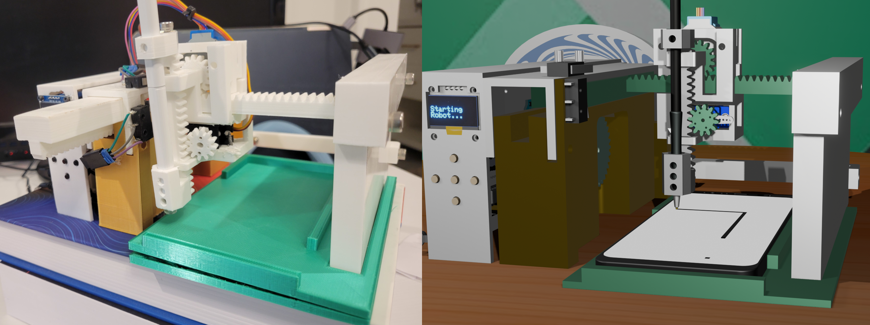
I had an itch to test my rapid prototyping skills. During the summer I gave myself 2 weeks to design, build, and program a cartesian robot from scratch. I wanted the architecture to be completley custom, without a lot of outside research that would bias my design from my own raw ideas. The project was a success, but because I was working in isolation I definitely made a few mistakes that I've learned much from. I could easily do this again much better.
Anyway, that said... I the goal was to see if I could create a robot that worked similar to that of 3D printers and Laser Cutters. I designed the end effector to have an interchangeable interface for cylindrical tools like a pen or X-acto knife. I did this project prior to my Laser Cutter build which you can learn more about here: Laser Cutter Design. This project certainly laid the ground work for that laser cutter and resulted in a fun little desk machine. Don't mind the wacky gold and green coloring - I had to work with the old PLA I had on hand.
The manufacturing industry has widely used the term "Cartesian robot" to describe a robot with a linear actuator and a linear drive system. These robots are often used in industrial automation and are commonly found in assembly lines, 2D plotting machines, 3D printers, and CNC machines. They are easily adopted because the hardware and setup is cheap, modular, and easy to program.
The robot typically features 3 linear actuators or rotary motors built on belt drives or rack and pinions to drive highly accurate and easily repeatable X-Y-Z motion. Because of the simplicity of the design, programming the robots and solving the kinematics is as simple as mapping each independent axis actuation to the respective X, Y, and Z coordinates. The frames are made of sturdy materials with vibration resistant fasteners and damping systems to ensure stability and longevity. The end effector can easily be swapped out for different tools according to the task need like a 3D printer extruder or a CNC drill. With all this in mind, this task was slated as fairly simple to execute for me once I had the materials and parts.
The whole system was designed without any references or research so I often went with the first idea that came to mind. I decided to make use of a rack and pinion drive system for all 3 Axis. I am well experienced with the Fusion FM Gears add on which is a great tool for procedurally generating gears. I love it because it can do basic gears, internal gears, and rack and pinion gears. You can also specify the number of teeth, pressure angle, and module size, pitch diameter, etc.
My familiarity with this tool and curisoity with the different gears I could make encouraged me to use them for the entire drive system. I know most systems use belts and rotarty motors, but I didn't have belts on hand or high torque rotary motors that were as small as I needed. I was aiming for something that fits neatly on a desk and most printable parts should be able to fit on my Ender 3 8"x8" build plate. The total range of motion of the robot is about 5"x8"X1" which isn't big, but can fit automated tasks like drawing, engraving, or tapping on a small screen or card.
Because the Cartesian robot uses rack and pinion gears for all three axes, each step of the stepper motor translates into a specific linear motion. Solving the forward kinematics is straightforward: each axis is decoupled, and the motion can be computed by understanding the relation between stepper motor rotation and rack linear displacement.
The linear travel per motor step is determined by the pitch diameter of the gear and the number of steps per revolution of the motor. For rack and pinion systems, the linear travel per revolution is equal to the circumference of the gear:
travel_per_rev = π × pitch_diameter
steps_per_inch = steps_per_rev / travel_per_rev
linear_distance = steps / steps_per_inch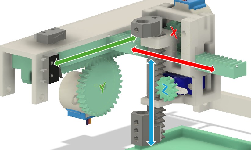
Here's how it works for each axis in this design:
So if you want to move the X axis by 1 inch, you’d send approximately 815 steps to the X stepper motor. The inverse kinematics are equally simple: desired linear motion is multiplied by steps/inch to calculate how many steps to send:
steps = desired_inches × steps_per_inchThis simple and deterministic mapping is one reason Cartesian robots are so reliable and easy to control. There’s no complex trigonometry or matrix math—just good old linear math and gear ratios.
All the 3D models for the hardware printed for the robot can be found here: 3 Axis Cartesian Robot Drive 3D Printable CNC Plotter 3D print model
You can support me on CGTrader, or you are free to download these free models from the Brevengineering Repository Or find a free pack here: 3D Printable CNC Plotter 3D print model
The electronics are fairly simple, but there are a handful of components. Everything was chosen to work with an arduion MEGA, althought the 3D model shows an UNO. Previously, I figured there was enough space for the Adafruit LCD libraries and stepper libraries, but I was running out of memory on the UNO. The MEGA has plenty of space and I was able to add a few more features, additionally, for all the I/O I really wanted to use, the MEGA was a better choice.
Here is a short BOM for the electronics and an electronics schematic:
| ID | Component | Qty |
|---|---|---|
| 1 | Push Button | 5 |
| 2 | SSD1306 OLED Display | 1 |
| 3 | 21g Mini Digital Servo | 1 |
| 4 | 12V (min 3A) Power Supply | 1 |
| 5 | Rocker Switch 2-pin SPST | 1 |
| 6 | Limit Switch (Y axis) | 2 |
| 7 | Buck Converter LM2596 12V→5V | 1 |
| 8 | 28BYJ-48 Stepper + ULN2003 Driver | 2 |
| 9 | Arduino Mega 2560 | 1 |
| 10 | 10kΩ Potentiometer | 2 |

It took some finangling to get the mega to fit where the arduino UNO was supposed to go, but I was able to make it work. The wiring is simple. If you use the ULN2003 Breakout boards that support direct pin connections from the steppers, motors it makes the wiring nicer. You may notice that the Z axis isn't actually a stepper motor. It's a servo. While one could program the machine to work as defined in our kinematic section, I found that my application was better done with an inprecise servo that just went to an on off location. This could be changed by reviewing the code and exchanging the hard coded servo locations, for relative rotations. I didn't do this because when it comes to drawing, stamping, etc. I found I just need the tool to go do and then go back up.
The robot controller takes advantage of the servo.h and stepper.h libraries for motor control inline. The approach allows motors to move simultaneously to perform multi-axis movements, which you don't get with typical motor libraries.
The code is written in C++ and is designed to run on an Arduino Mega 2560. The code is fairly simple, but it does require some understanding of the Arduino libraries and how to use them.
The code is available on my GitHub page: 3AxisMachine
The code is fairly simple, but it does require some understanding of the Arduino libraries and how to use them.
Stepper library to control the stepper motors.Servo library to control the servo motor.Wire library to communicate with the SSD1306 OLED display.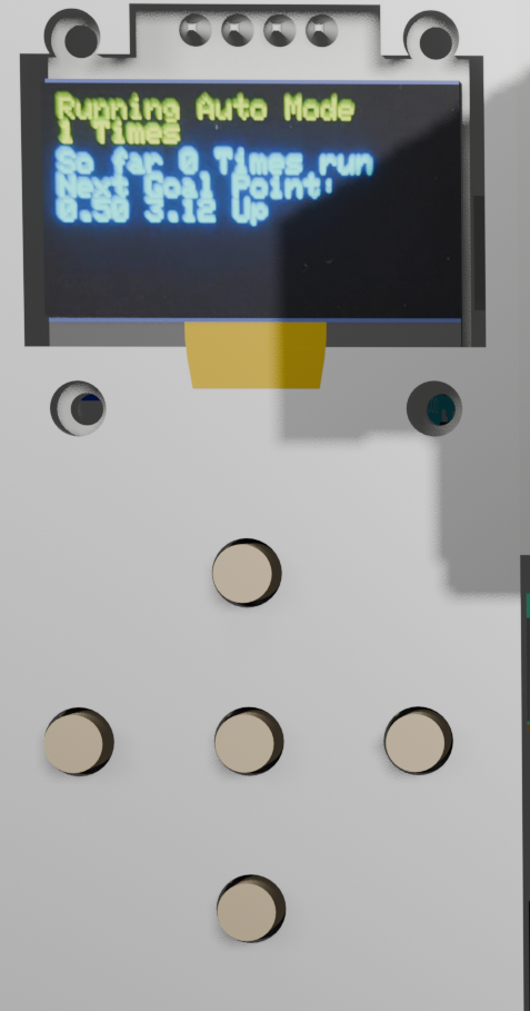
The idea behind the code is a state machine. The state machine is a simple way to manage the robot's behavior. It's a finite state machine that can be in one of a few states. The states are:
See the robot in action! The robot is capable of performing a variety of tasks, including drawing and tapping on a small screen.
All source code for this project and steps on how to run it can be found on my github page.