This was a team project from a graduate haptics course at Johns Hopkins University. The goal was to build a wearable haptic glove
capable of simulating the sensation of touching a virtual wall. When a user bends their finger past a defined threshold position,
the device physically resists further motion — creating a convincing illusion of contacting a rigid surface.
The core concept is rooted in impedance control: rather than commanding position directly, the controller measures
the user's finger position and generates a resistive force proportional to how far the finger has penetrated the virtual wall.
This is the mechanical equivalent of a spring — the deeper you push, the harder it pushes back.
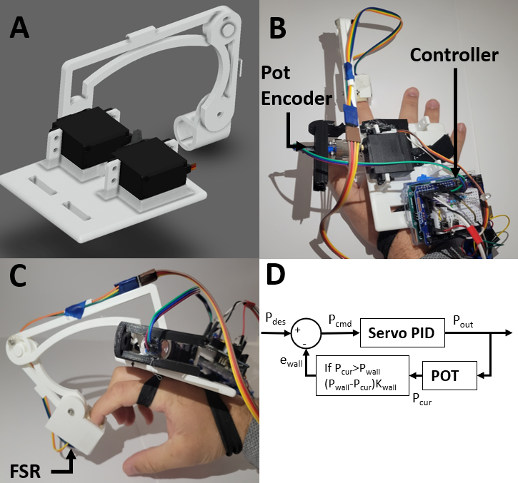
Fig.1 Assembled haptic glove prototype.
The project went through several hardware iterations before landing on a working solution. We initially targeted multi-finger
coverage with quadrature encoders and DC motors, but hardware limitations forced us to simplify to a single-finger servo-based
design. The final device uses a modified hobby servo as both actuator and position sensor, FSR sensors to detect contact force
at the fingertip, and an RGB LED to communicate device state. All structural parts were custom 3D printed.
The wall threshold is set interactively — the user holds their finger at the desired wall position and presses a button,
and the system records that angle as the virtual boundary. A second button toggles wall rendering on and off. This made the
device usable as a proof-of-concept demo for a standard male hand without any pre-calibration.
Hardware Evolution
The design went through two major hardware phases before arriving at the final working prototype. Each phase taught a hard lesson
about sensor resolution, actuator coupling, and the importance of matching hardware to the control problem.
1
Optical Encoders + DC Motors
Abandoned
Our original plan was to use DC gearbox motors paired with optical wheel encoders on each finger. The encoders (20 slots, 40
events per revolution) gave us quadrature position feedback via interrupts on an Arduino Mega. However, with only
4.5° of angular resolution per count, the system could not detect the fine finger motions needed for smooth
haptic feedback. A finger joint that moves through only 30–50° of useful range has barely 10 distinct positions — far too coarse.
The geared motors also introduced substantial backlash and were too stiff to allow natural free motion between wall contacts.
2
Servo Bypass — Potentiometer Position Sensing
Final Solution ✓
We pivoted to a cheap MG996R hobby servo. Rather than using it as a standard PWM servo, we bypassed the internal
potentiometer circuit — soldering wires directly to the pot terminals — so we could read raw voltage on an analog input
pin. This gave us continuous, high-resolution position feedback over the full range of motion. With a 10-bit ADC and
linear calibration, effective angular resolution improved to roughly 0.3° per count — a 15× improvement over
the encoder approach.
The servo was coupled to the index finger using a 3D printed saddle and rigid link. A safety decoupler was
incorporated so that excessive actuator force would disengage rather than injure the user's finger. We had previously explored
a wire-and-pulley transmission for multi-finger coverage, but this proved too mechanically complex to implement reliably
within the project timeline, and was dropped in favor of a single-finger proof of concept.
3
Fingertip Force Sensing (FSR)
Force Sensitive Resistors embedded in a fingertip cap measure contact force when the user presses against a physical surface.
Two FSRs (A4 and A5) provide front and back contact readings. In the admittance controller prototype they served as the primary
input signal; in the final impedance controller they provide supplemental contact telemetry. The FSR data is also used to
trigger the MOSFET gate controlling servo power.
Electronics & Wiring
The final circuit is built around an Arduino Nano and uses the following components:
MG996R servo (pot bypassed) — digital pin 9 via Arduino Servo library
Internal potentiometer (wire tapped) — analog pin A0
FSR sensors — analog pins A4 and A5
RGB LED — analog write on A1 (R), A2 (G), A3 (B)
MOSFET driver — pin 8, gates servo power on/off
Wall-set button — pin 6, INPUT_PULLUP, records current finger position as wall
MOSFET safety logic: On startup the servo homes to 90° with the MOSFET enabled. After homing it drops low,
leaving the servo unpowered so it doesn't fight free finger motion. The MOSFET only re-engages when wall contact is detected —
applying torque only when resistance is actually needed.
The first hardware iteration used an Arduino Mega with a dual H-bridge motor driver for DC motor control.
Encoder CHA/CHB channels used hardware interrupt pins 2 and 3. The Mega was chosen specifically for its additional
interrupt-capable pins to support up to three motor encoders.
Fig.2 Haptic rendering and control architecture diagram.
Control Theory & Math
Impedance Control — Final Design
Impedance control renders a virtual mechanical impedance at the user's fingertip. When finger position
q exceeds the wall threshold qwall, the controller generates a resistive
reference position that pushes back against the penetration. The virtual wall behaves like a spring:
if q > qwall :
ref_pos = q − kwall × (q − qwall)
With k_wall = 0.5, the servo is commanded halfway back for every degree of penetration — a progressive
resistance that feels stiffer the harder you push. The gain was tuned empirically: lower values felt too soft,
higher values caused oscillation from servo lag.
The raw potentiometer signal is noisy. An exponential smoothing filter (first-order IIR low-pass)
conditions the reading before it enters the control law:
With α = 0.1 the filter has a time constant of ~9 samples — enough to suppress noise while
staying fast enough for natural hand motion. The filtered ADC value is then converted to degrees via linear calibration:
q [deg] = 0.4977 × smoothed − 240.98
Admittance Control — First-Attempt DC Motor Design
The DC motor prototype used admittance control — the dual of impedance control. Instead of the
device resisting position with a force output, it accepts a force input (from the FSRs) and responds with motion.
The admittance model is a virtual mass-damper:
Ma &ddot;xref + Ba ˙xref = Fext
Discretized via Tustin's (bilinear) method at Ts = 1/200 s:
With k = 5 (stiffness) and b = 1 (damping). This is the bilinear-discretized form of the
spring-damper impedance Z(s) = ks + b.
PID with Dirty Derivative Filter
The admittance law produces a reference position that a PID loop tracks via encoder feedback. The derivative term
uses a dirty derivative (filtered derivative) to avoid amplifying encoder quantization noise:
Filter constant σ = 0.05. PID gains: Kp = 560, Kd = 10.01, Ki = 0.
Integral was left at zero — steady-state error was acceptable for haptic rendering and adding integral would have
introduced wind-up risk during wall contact.
Arduino Code
Final Controller — NanoServo.ino
This is the working firmware for the servo-based impedance glove. Full source:
NanoServo.ino.
if (!digitalRead(wallsetbut)) {
    wall1pos = cur_ref1;  // record current position as virtual wall
}
if (!digitalRead(wallactbut) && millis() - oncycletime > 2000.0) {
    wallson = !wallson;
    oncycletime = millis();
}
The final servo-based device successfully demonstrated virtual wall rendering on a single finger. When the wall was enabled,
users felt a clearly perceptible resistance upon crossing the programmed threshold — qualitatively similar to pressing
against a foam block. The RGB LED made device state immediately legible without looking at the controller:
Green — walls active, finger in free space
Red — wall contact detected
Blue — wall rendering disabled
Key insight: The servo potentiometer approach gave ~0.3° effective resolution vs. 4.5°/count with the
optical encoder — a 15× improvement that made the difference between a working haptic device and
an unstable one.
The FSR readings confirmed contact events and their magnitude, though not fully integrated into the final impedance loop —
they provided useful telemetry during testing. The 2-second debounce on the wall toggle prevented accidental state changes
during demos.
If we continued development, the highest-value next steps would be extending to a second finger using a second servo,
adding a proper wiring enclosure, and running a psychophysical study to characterize stiffness perception vs.
k_wall across subjects.