A common application of robotics is to have the robot manipulate objects in 3D space with the task
to orient an object or place an object in a specific spot. There are many ways to accomplish this task with
the most basic idea revolving around having the robot measure its own position in 3D space using its sensors/encorders and forward kinematics (FK).
The robot operator may have the robot move to predifined locations, but this proves impractical when the robot needs to operate
in an unpredictable or constantly changing environment.
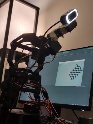
Fig.1 Revyn Arm with webcam attached.
A better approach would be to couple the FK and sensors with a camera to give the robot 'computer vision.' In this project
I use a common method for integrating a camera with a robot arm where a camera is attached near the end effector and moved
about the 3D space to locations where a clear and easily defined target can be identified. With these targets in frame, computer
vision algorithms can decifer what objects are within the image and compute the predicted position and orientation of the object
relative to the camera. We can gather several sets of camera to calibration object poses and several corresponding sets of end
effector to robot base poses. With these elements we can identify a transformation between the end effector pose to the robot attached
camera pose that enables the camera to understand where objects in the image are relative to the robot base.
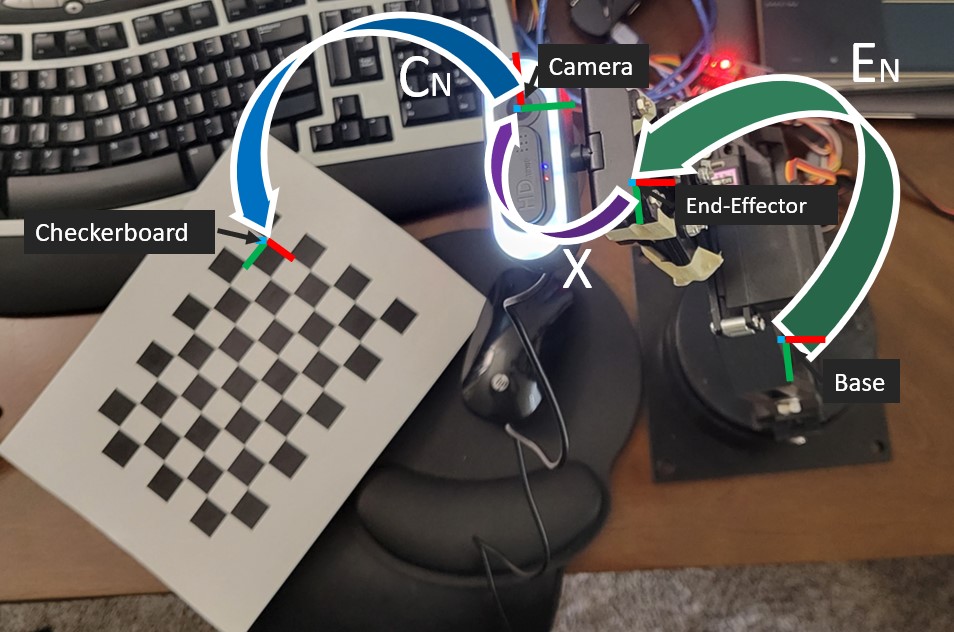
The project presented here can be described as a complex linear algebra problem where we are solving
for a homogenous transformation 4x4 matrix X as shown in figure 2, where we have intrinsic transformation difference matrices A and B to help us.
We will find X in AX=XB by building A and B matrices made of several base to end effector transformation matrices and several
corresponding camera to checkerboard frame transformations respectivley. We use a checkerboard as it is an easily identified object
in computer vision with a defined height and width. I used OpenCV to recognize the checkerboard and find the transform between the camera and the checkerboard.
I'll discuss the camera to checkerboard calibration later.
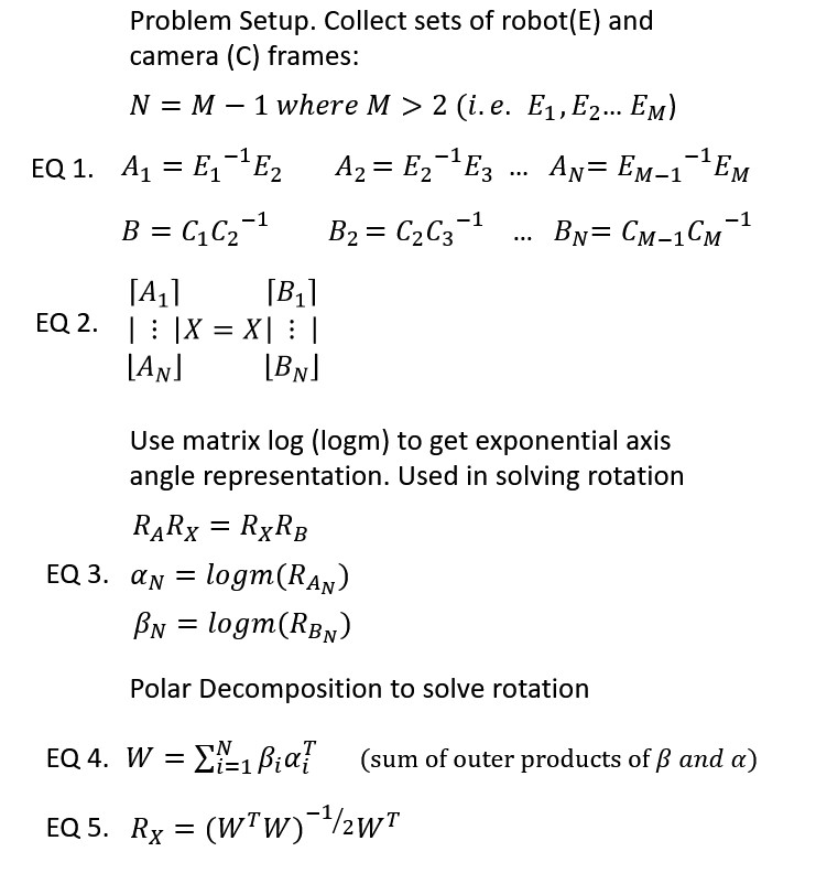
The solution to X is shown in figure 3. The steps are as follows. Refer to E and C in figure 2, we collect
at least 3 (preferably more than 10) sets of frames E and C by moving the robot to a location where we know the
position and orientation of the end effector relative to the base and the camera can succesfully find a transform between itself and the checkerboard.
With these frames we build the intrinsic difference matrices A and B. A is the transform between two end effector positions. B is the reverse transform between
two camera positions. See EQ 1.
We set the problem up as in EQ 2.
Fig.3 Solution to Rx.
The rotational portion of X, Rx is solved using the matrix log of each A and B matrix. The matrix
log returns an exponential axis-angle representation of a rotation matrix. This gives us vectors alpha and beta
can be used to sum up the outer product of each alpha and beta in EQ 4. and with EQ 5. polar decomposition to get the rotation matrix Rx.
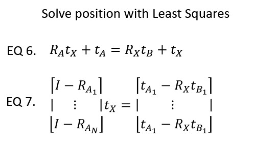
We solve for tx, the position portion of X using a Least Squares approach. We needed Rx first to
get equation EQ 2. to look like EQ 6. We solve EQ 7. using the matrix psuedo-inverse or an SVD
Fig.4 Solution to tx.
With both Rx and tx we have X, the homogeneous transformation matrix between the robot end effector and the camera and can move the robot in 3D space
towards objects more intelligently.
Camera Undistortion and Checkerboard Framing
The biggest hurdle encountered in the calibration project was not calibrating the robot, but
correctly compensating for the camera physics. The camera I used in this project
was a fairly poor and cheap webcam. The camera used a fisheye lens with heavy distortion and some less than favorable
specifications. The goal was to use the camera with OpenCV's findChessboardCorners function and solvePnP function to identify what the frame
in the corner of the checkerboard is relative to the camera. To use those functions, however, you need to remove as much error and distortion in the
camera image as possible. Thus, I calibrated the camera with the OpenCV fisheye get camera extrinsic properties functions. See my FishCal.py script.
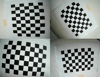
To do this, I collected a lot of calibration images where the camera was placed around the extreme areas of the checkerboard to help define the distortion physics.
This allowed me to find a K and D matrix that could undistort the points of the checkerboard.
Fig.5 Example Camera Calibration Images.
With these points I used the SolvePnP method which takes a set of known 3D object points (where the checkerboard inner square corners are) and compares them
to where they have been found in a 2D image array of the findChessboardCorners function. The Checkerboard used in my project had 20mm wide squares and the chessboard in the
images was assumed to be at a Z=0 level. Therefore the array of squares simply incremented across a flat plane of 20mm squares, the dimensions of which are 6x9.
SolvePnP returned a rotation vector and translation vector which was used to build a homogeneous tranformation matrix, C, with the rotation and translation of the checkerboard relative to the camera. More details for this can be seen in the code CheckerFramePlace.py.
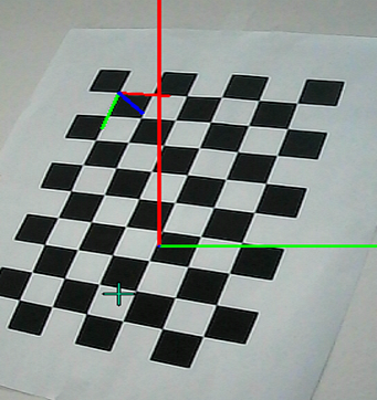
Fig.6 Frames placed on the camera image.
The resulting C tranform was plotted on the live image of the camera in the corner of the chessboard. I also
designed the code to plot the camera's own frame on the front of the image (where we are looking down the Z axis of the camera) as shown in figure 6 with the chessboard corner in the top left
and the center frame is the camera's own frame.
With this calibration complete, we could capture C frames with this frame placer and E frames with the robot FK and solve the AX=XB problem.
Calibrating the Robot and Observing the Error
In my tests I fixed the Checkerboard to a white piece of sturdy cardboard. I fixed the robot, the board, and the camera
so they would be rigid and not move. If any of them move during the calibration process then the calibration wouldn't work.
I moved the robot to 13 different locations caputing 13 E and C frames. The following video shows how I commanded the robot to move to
a point where the checkerboard was in frame and a successful frame was placed on the checkerboard (as you can see on the computer monitor).
The execution of the calibration can be found in the XCAL_Test.py script
where the resultant camera frames and end effector frames including X are plotted and the calculated error between my predicted frames and the real world checkerboard frame is shown.
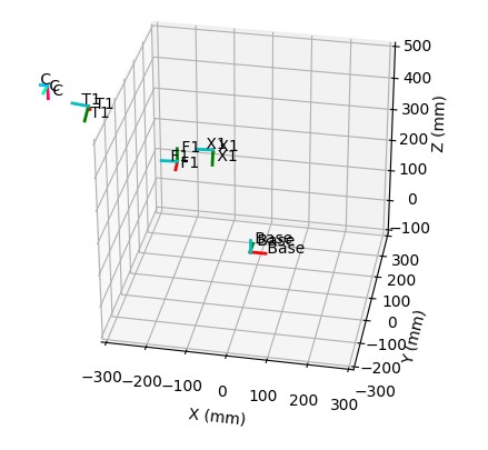
Fig.7 Virtual Calibration Results
Figure 7 shows the result of my calibration where C is the true location of the checkerboard relative to the base (hand measured),
F1 is the end effector for position 1, X1 is the transform from F1 to the camera, and T1 is where the robot thinks the checkerboard is
given my calibration. As you can see the calibration is less than stellar, but this is because my images did not have enough diversity of angle.
Most of the images were taken from the similar locations of the robot and since the robot is so short I could not get good shots of the checkerboard
above or to the sides of it. This heavily skewed the Z calibration of the X frame. You can see that it does fairly well to calculate
the X an Y however. The Resulting X matrix can be found by running my script, and some general errors are shown below. All dimensions are in mm and the following
errors were found by finding the standard error between each calibrated predicted frame (T1,T2..etc) and the true frame C
Calibration Error Results:
X: ±15.7 mm | Y: ±28.9 mm | Z: ±29.8 mm
Typical error of 2–4 cm — expected given the consumer fisheye webcam and hobby-grade servo inaccuracies. The Z axis was most affected by limited pose diversity during capture. Recalibrating with more diverse angles, 20+ poses, and a better-quality camera would significantly tighten these numbers.
Resources
All source code for this project can be found on my github page.
Check out how to use OpenCV's SolvePnP function for finding transformations with 3D Homography.